Blog 2: Arduino Programming
- nicholasleejh05
- Dec 8, 2024
- 19 min read
Hello and welcome back to my blog! Today, I will share more about my journey in the past few weeks and I have so much to share. Let's jump right into it!
In this blog, I will introduce you to Arduino programming! Initially, I didn't enjoy programming because of my experience in 2022 when I used a Micro:bit. I worked on combining it with other components to create a product for a module, but the process didn’t resonate with me at the time. The main reason was because of the programming part, where I took 6 hours to finish a simple code. Hence, when I heard about Arduino programming, I wasn't excited compared to the previous blogs. Here I am two years later doing programming again, but this time with an Arduino board.
Arduino

What is Arduino or Arduino programming? Arduino is an open-source electronics platform based on easy-to-use hardware and software. Arduino boards can read inputs, such as light on a sensor or a finger pressing a button, and convert them into outputs, such as activating a motor or turning on an LED! To achieve this, the Arduino follows a set of instructions written in a programming language, which in this case is C++. One fun fact I learned about programming while writing this blog is that there are over 8000 programming languages. However, only a few languages such as C/C++, Java/JavaScript, and Python are popular in the IT industry! The Arduino board reminds me of my desktop motherboard.
You might be wondering, "How do I use it?" or "What am I exactly seeing from this Arduino board?". We first need to understand what each component of the Arduino board does with the help of a picture down below.

Now, what else? We need to transfer a set of instructions into the Arduino board for it to work with the help of software! There are different software that can help transfer the instructions into the Arduino board but today, we are only going to use Arduino IDE as it is the most compatible and free to use! I have linked the website to download the Arduino software: https://www.arduino.cc/en/software

With both the hardware and software done, you can still create cool things such as an on/off button that can play music. However, I highly recommend getting a few things in the picture down below to take it to another level!

Additionally, I also recommend watching the video down below to grasp more of the basics of Arduino. It teaches you how to properly set up your very own Arduino board!
Now that you understand the basics of Arduino programming, let's move on to the next part of the blog!
Input Devices
It is time for the juicy part of the blog! Recently, we were given an assignment to complete on Arduino programming. For this part of the assignment, we were tasked to do one of the two.
Interface a potentiometer analog input to Maker UNO board and measure/show its signal in serial monitor Arduino IDE.
Interface a LDR to Maker UNO board and measure/show its signal in serial monitor Arduino IDE.
Even though we had to choose either one of the tasks, I will be doing both as I think it is a good practice for my chemical product project. Additionally, I will also be explaining how it works and how to set it up!
Potentiometer
For this task, I decided that I wanted to do something different that is more challenging even though I am very bad at programming. However, if it is more challenging, I get to learn more new things which helps to achieve my goal! Moving forward, in order to complete this task, we have to firstly understand what is a potentiometer. To put it simply, a potentiometer is a variable resistor that allows the voltage in an electrical circuit to be adjusted. There are many uses of a potentiometer such as adjusting the brightness of it! Now that I think about it, a potentiometer is basically an electric version of the hydraulics.
You may be wondering, what is my idea for this task? My idea is when the potentiometer is increasing, the brightness of LED in pin 12 and 13 will increase and decrease respectively. Once I have decided on my idea, it's time to decide on the materials required which are shown down below.
Materials required:
Breadboard
Potentiometer
Arduino board
Any 3 wires

Now that we have the materials required, how do we set it up? We need to first understand the pin layout of the potentiometer using the picture on the right. This is a very important! It's time to assemble to components required!
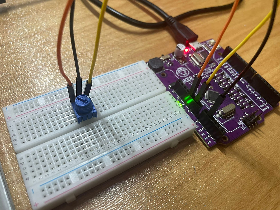
Connect a wire from 5V of the potentiometer to 5V pin on the Arduino Board. (Orange wire)
Connect a wire from VOUT of Potentiometer to A1 pin on the Arduino Board (Black wire)
Connect a wire from the GND of the potentiometer to the GND pin on the Arduino board
Now that we have connected the wires correctly, it's time to program it to work! For this section, I used ChatGPT to come up with the code. Even though I used ChatGPT to help me with the code, I fully understood everything. To prove it, I will be explaining how the code works. Firstly, it’s important to understand that the Arduino board executes code from top to bottom, executing one instruction after another until the program finishes which is similar to following each step of a recipe to prepare a dish.
int potPin = A1;
int potValue = 0;
void setup() {
  Serial.begin(9600);
}
void loop() {
  potValue = analogRead(potPin);
  Serial.println(potValue);
  delay(50);
}
The code above is very simple to understand, even a beginner like me understand what happens.
int potPin = A1;
int potValue = 0;
int potPin = A1 is used to represent the analog pin A1, where the potentiometer is connected.
int potValue = 0 is the value of the potentiometer at the start.
void setup() {
  Serial.begin(9600);
}
Void setup () is executed one time at the beginning of the code.
Serial.begin(9600) is used to to allow the Arduino to communicate with the Serial Monitor at 9600bit/s (bit per second)
void loop() {
  potValue = analogRead(potPin);
  Serial.println(potValue);
  delay(50)
Void loop() function runs repeatedly in a continuous cycle. This means that any code between the curly brackets will run infinitely.
int potValue = analogRead(A1) reads the value from the potentiometer which is connected to A1. The value ranges from 0 to 1023 depending on the potentiometer knob's position.
Serial.println(potValue) shows the value of the potentiometer and displays it in the serial monitor.
Delay(50) is a function that waits for 50 miliseconds.
Now that you have finished the coding, it should be similar to the thing down below.
You may be wondering, what is my idea for this task? My idea is when the potentiometer is increasing, the brightness of LED in pin 12 and 13 will increase and decrease respectively. Once I have decided on my idea, it's time to decide on the materials required which are shown down below. Hence, I used ChatGPT to help improve this even further.
void setup() {
  pinMode(12, OUTPUT);
  pinMode(13, OUTPUT);
  int potPin = A1;

  Serial.begin(9600);
}

void loop() {
  int potValue = analogRead(A1);

  int brightness12 = map(potValue, 0, 1023, 0, 255);
  int brightness13 = map(potValue, 0, 1023, 255, 0);

  analogWrite(12, brightness12);
  analogWrite(13, brightness13);


  Serial.print("Potentiometer Value: ");
  Serial.print(potValue);
  Serial.print(" | LED 12 Brightness: ");
  Serial.println(brightness12);
  Serial.print(" | LED 13 Brightness: ");
  Serial.println(brightness13);

  delay(5);
}
There are two key points to take not of when programming, the first is when using void setup() or void loop() , insert the code between the the curly brackets "{ }" as shown above so that the Arduino board will understand when it will start or stop for that section. The second is to always include the semicolon (;) after the function to allow the Arduino board to understand where to statement ends.
void setup() {
  pinMode(12, OUTPUT);
  pinMode(13, OUTPUT);
  int potPin = A1;

  Serial.begin(9600);
}
Void setup () is executed one time at the beginning of the code.
pinMode(12, OUTPUT) and pinMode(13, OUTPUT) are used to set the pins on the Arduino as the output. In this case, the pins are connected to the LEDS.
int potPin = A1 is used to represent the analog pin A1, where the potentiometer is connected.
Serial.begin(9600) is used to to allow the Arduino to communicate with the Serial Monitor at 9600bit/s (bit per second)
void loop() {
  int potValue = analogRead(A1);

  int brightness12 = map(potValue, 0, 1023, 0, 255);
  int brightness13 = map(potValue, 0, 1023, 255, 0);

  analogWrite(12, brightness12);
  analogWrite(13, brightness13);


  Serial.print("Potentiometer Value: ");
  Serial.print(potValue);
  Serial.print(" | LED 12 Brightness: ");
  Serial.println(brightness12);
  Serial.print(" | LED 13 Brightness: ");
  Serial.println(brightness13);

  delay(5);
}
Void loop() function runs repeatedly in a continuous cycle. This means that any code between the curly brackets will run infinitely.
int potValue = analogRead(A1) reads the value from the potentiometer which is connected to A1. The value ranges from 0 to 1023 depending on the potentiometer knob's position.
int brightness12 = map(potValue, 0, 1023, 0, 255) Maps the potentiometer value (ranging from 0 to 1023) to the brightness value (range from 0 to 255). It sets the limits of the potentiometer and brightness value and anything beyond that is ignored. Additionally this code results in a linear relationship.
int brightness13 = map(potValue, 0, 1023, 255, 0) Maps the potentiometer value (ranging from 0 to 1023) to the brightness value (range from 0 to 255). It sets the limits of the potentiometer and brightness value and anything beyond that is ignored. Additionally this code results in a non-linear relationship.
analogWrite(12, brightness12) and analogWrite(13, brightness13) adjusts the the brightness of the LED on pin 12 and 13 by adjusting the voltage based on the value of brightness12 and 13 respectively.
Serial.print("Potentiometer Value: ") send the text of potentiometer value to the serial monitor.
Serial.print(potValue) sends the value of current flowing through the potentiometer which ranges from 0 to 1023 to the serial monitor.
Serial.print(" | LED 12 Brightness: ") and Serial.print(" | LED 13 Brightness: ") sends the text of the LED brightness to the serial monitor which ranges from 0 to 255.
Serial.printIn(brightness12) and Serial.printIn(brightness13) holds the brightness value for the LED connected to pin 12 and 13 respectively.
delay(5) waits for 5 milliseconds before reading the next code.
That's enough explanation for now, my brain hurts.... Now that you have understood what each code does, you can copy the code below and press the arrow button on the top left. This will send the instructions from your computer into the Arduino board! Once done, it should work like the video shown below.
While completing the task, I didn't face much difficulty other than uploading a video that is in high quality. The only other difficulty was when I connected the voltage output wire into pin13 instead of A1. This problem was easily solved as since it did not work on the digital (PWM) pins, it must work on the analog in pins! For the breadboard, I did not had any difficulty due to the prior experience I had with it during my PFP year where I used it for my physics lesson. Additionally, I did face what it seems to be a strange encounter. Initially, I wanted to connect the GND wire (yellow) to pin 13 as I assumed it to be the voltage output wire. However, I misplaced it and connected to the GND pin which caused it to work. I figured this out because I went to check the video retakes I took on the first try. Now that we have completed the first task, it's move onto the next one! Yippee!
LDR
For this activity, I decided to do a basic LDR as I couldn't think one that would be a challenge. Hence, I decided to the basic one. What is an LDR? A LDR is a light dependent resistor changes the voltage passing through depending on the intensity of the light. Once I understood that, it's time to decide on the materials required which are shown down below.
Materials required:
Breadboard
Arduino board
Photoresistor
Resistor
4 wires
Now that we have our material ready, it's time to insert the wires as shown down below.

Once completed, we need to add in the coding! I obtained the code from the Maker UNO Edu Kit Module slides which were very helpful!
int LDR = A0;
int ledPin = 9;
int LDRvalue = 0;
void setup()
{
pinMode(ledPin,OUTPUT);
}
void loop()
{
LDRvalue = analogRead(LDR);
if(LDRvalue > 900)
digitalWrite(ledPin, LOW);
else
digitalWrite(ledPin, HIGH);
}
Similar to the previous task, I am going to walk you through how the coding works, what difficulties I had faced and how I overcame it.
int LDR = A0
int ledPin = 9
int LDRvalue = 0
int LDR = A0 is to inform the Arduino board that the LDR Is connected at pin A0.
int ledPin = 9 is to inform the Arduino board the LED is connected at the digital pin 9.
int LDRvalue = 0 is used to store the LDR's value.
void setup()
{
pinMode(ledPin,OUTPUT);
}
Void setup () is executed one time at the beginning of the code.
pinMode(ledPin, OUTPUT) are used to set the pins on the Arduino as the output. In this case, the pins are connected to the LEDS.
void loop()
{
LDRvalue = analogRead(LDR);
if(LDRvalue > 900)
digitalWrite(ledPin, LOW);
else
digitalWrite(ledPin, HIGH);
}
Void loop() function runs repeatedly in a continuous cycle. This means that any code between the curly brackets will run infinitely.
LDRvalue = analogRead(LDR) reads the voltage of the LDR and converts the value into a range of 0 to 1023. It is directly proportional.
if(LDRvalue > 900) else compares the value of LDRvalue which is the light intensity with the condition of 900.
digitalWrite(ledPin, LOW) if it meets the condition that is if the light intensity is above 900, the LED in pin 9 will be switched off.
digitalWrite(ledPin, HIGH) if it dosen't meet the condition that is if the light intensity is below 900, the LED in pin 9 will be switched on.
Woohoo! You now understand what it does and how it works! Give yourself a pat on the back! Additionally, the condition of LDRvalue > XXX can be modified depending on the light intensity of your light source. When done correctly, it should work just like the video down below.
Even though this task seems easy, I had difficulty troubleshooting it. This is because initially, I put LDRvalue > 600. This small but important code caused me to try troubleshooting for half a minute. I tried to several methods to troubleshoot. The first thing I did was the change LDRvalue > 600 to LDRvalue < 600. The second thing was to add codes such as Serial.begin(9600) as I thought that the instructions was not transferring to the Arduino board. The third thing I tried was to change the circuit of the board as I assumed that the circuit was wrong. I also tried to change the wires as I assumed it could be a faulty wire. However, none of this solutions worked. At one point, removing the 5V pin caused it to turn on the LED light which got me confused for a moment. Finally, since different light source had different light intensity, the LDRvalue > XXX had to be calibrated in order for the circuit to work. This idea came about when I wanted to switch my lamp on and off which might seem weird but it isn't. This is because my lamp had white and yellow light, when there was a white light, the pin would not turn on, however, the pin would turn on when there was a yellow light. Hence, I adjusted the LDRvalue > XXX till it worked. After solving the problem, there was a sigh of relief. Now that we have completed this task, it is time to move onto the next part of the blog! Yay!
Output Device
For this section of the assignment, we were tasked to interface 3 LEDs (Red, Yellow, Green) to Maker UNO board and program it to perform an action (fade or flash, etc). Use the pushbutton on the Maker UNO board to start/ stop the action. I decided to look up online for inspiration and found one which is interesting.
To modify the idea, I added the idea of a start/stop button that can turn on/off the lights and music. Similar to the previous tasks, it's time to decide on the materials required which are shown down below.
Materials required:
Arduino board
Breadboard
4 wires
3 resistors
3 LEDs
Now that we have obtained the materials needed, it's time to construct it! It should look similar to this.
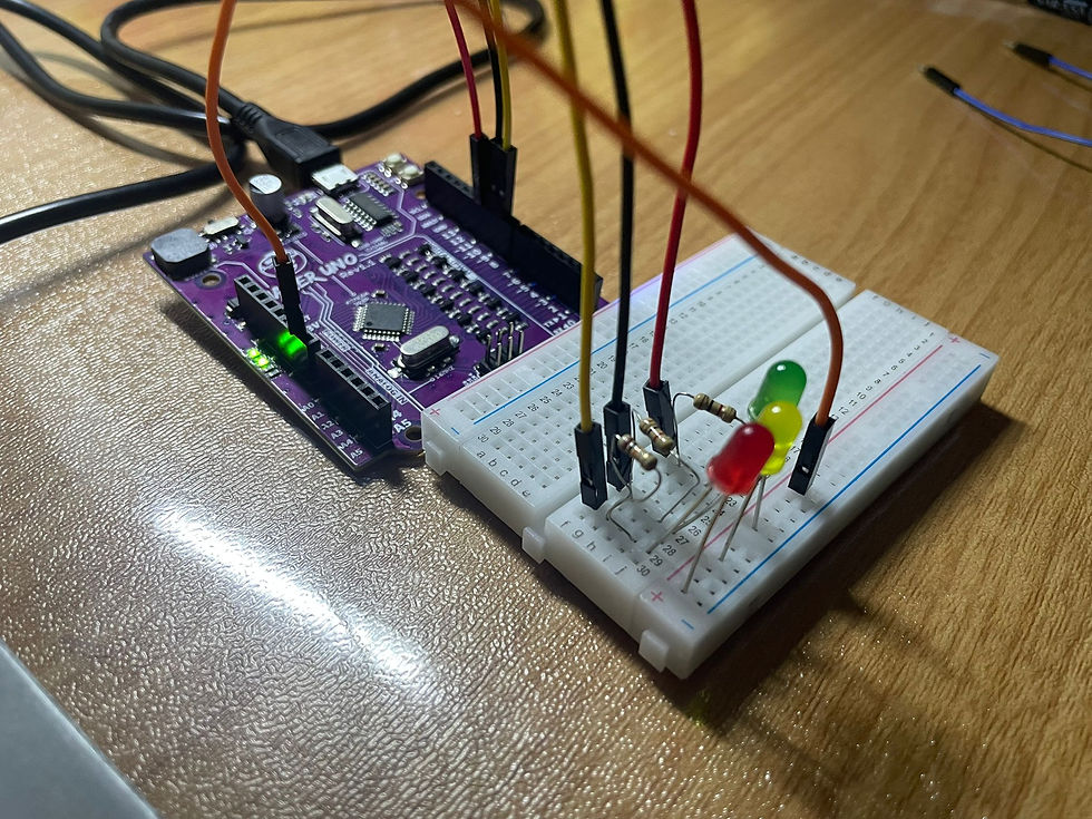

One key point to take note of is the pin layout of LED. The cathode should be connected on the power rails while the anode must be connected on the terminal strips of the breadboard. If not correctly, the LED will not work. Now that we have inserted our components into the breadboard, it's time to insert the code!

Similar to the previous tasks, I will also walk through with you on the explanation of the codes and what difficulties I faced while completing this task. For the coding section,I used ChatGPT because it is reliable and easy to use. I asked ChatGPT for help interfacing three LEDs and music that would play concurrently, controlled by a start/stop button..
int redLED = 9;
int yellowLED = 10;
int greenLED = 11;

int buzzer = 8;

int buttonPin = 2;


bool isChaseActive = false;
int lastButtonState = HIGH;
unsigned long lastDebounceTime = 0;
const unsigned long debounceDelay = 50;

int melody[] = {262, 294, 330, 349, 392, 440, 494};
int melodyIndex = 0;
const int noteDuration = 200;

void setup() {
  pinMode(redLED, OUTPUT);
  pinMode(yellowLED, OUTPUT);
  pinMode(greenLED, OUTPUT);

  pinMode(buzzer, OUTPUT);

  pinMode(buttonPin, INPUT_PULLUP);

  digitalWrite(redLED, LOW);
  digitalWrite(yellowLED, LOW);
  digitalWrite(greenLED, LOW);
  noTone(buzzer);
}

void loop() {
  int buttonState = digitalRead(buttonPin);
  if (buttonState == LOW && lastButtonState == HIGH && millis() - lastDebounceTime > debounceDelay) {
    isChaseActive = !isChaseActive;
    lastDebounceTime = millis();
  }
  lastButtonState = buttonState;

  if (isChaseActive) {
    ledChaseWithMusic();
  } else {
    turnOffSystem();
  }
}

void ledChaseWithMusic() {
  tone(buzzer, melody[melodyIndex], noteDuration);

  digitalWrite(redLED, HIGH);
  delay(noteDuration);
  digitalWrite(redLED, LOW);

  melodyIndex = (melodyIndex + 1) % 7;

  tone(buzzer, melody[melodyIndex], noteDuration);
  digitalWrite(yellowLED, HIGH);
  delay(noteDuration);
  digitalWrite(yellowLED, LOW);

  melodyIndex = (melodyIndex + 1) % 7;

  tone(buzzer, melody[melodyIndex], noteDuration);
  digitalWrite(greenLED, HIGH);
  delay(noteDuration);
  digitalWrite(greenLED, LOW);

  melodyIndex = (melodyIndex + 1) % 7;
}

void turnOffSystem() {
  digitalWrite(redLED, LOW);
  digitalWrite(yellowLED, LOW);
  digitalWrite(greenLED, LOW);
  noTone(buzzer);
}
This might be the longest code that I have ever "written".
int redLED = 9;
int yellowLED = 10;
int greenLED = 11;
int redLED = 9 is to store the pin numbers to which the red LED is connected on the Arduino board which in this case in pin 9.
int yellowLED = 10 is to store the pin numbers to which yellow LED is connected on the Arduino board which in this case in pin 10.
int greenLED = 11 is to store the pin numbers to which green LED is connected on the Arduino board which in this case in pin 11.
int buzzer = 8 is to store the pin number of where the buzzer is connected on the Arduino board which in this case is pin 8.
int buttonPin = 2 is to refer the pin number of where the button is connected on the Arduino board which in this case is pin 2.
bool isChaseActive = false;
int lastButtonState = HIGH;
unsigned long lastDebounceTime = 0;
const unsigned long debounceDelay = 50;
bool isChaseActive = false tracks whether the chase effect is active which in this case it's not.
int lastButtonState = HIGH holds the previous state of the pushbutton.
unsigned long lastDebounceTime = 0 keeps track of the last time the button was pressed. It is to ensure that the button is only triggered once.
const unsigned long debounceDelay = 50 is used to ensure that if a button is pressed within 50 miliseconds, it will be ignored.
int melody[] = {262, 294, 330, 349, 392, 440, 494};
int melodyIndex = 0;
const int noteDuration = 200;
int melody [ ] contains the frequency of the music in Hz which represents the notes of it. For example, 262 Hz = C4, 294 Hz = D4 etc.
int melodyIndex = 0 keep tracks of the current note
const int noteDuration = 200 controls the duration of each note in miliseconds, in this case it is 200 miliseconds.
void setup() {
  pinMode(redLED, OUTPUT);
  pinMode(yellowLED, OUTPUT);
  pinMode(greenLED, OUTPUT);

  pinMode(buzzer, OUTPUT);

  pinMode(buttonPin, INPUT_PULLUP);

  digitalWrite(redLED, LOW);
  digitalWrite(yellowLED, LOW);
  digitalWrite(greenLED, LOW);
  noTone(buzzer);
}
Voidsetup() is executed one time at the beginning of the code.
pinMode(redLED, OUTPUT) is used to set the redLED pin on the Arduino as the output which is pin 9.
pinMode(yellowLED, OUTPUT) is used to set the yellowLED pin on the Arduino as the output which is pin 10.
pinMode(greenLED, OUTPUT) is used to set the greenLED pin on the Arduino as the output which is pin 11.
pinMode(buzzer, OUTPUT) is used to set the buzzer pin on the Arduino as the output which is pin 8.
pinMode(buttonPin, INPUT_PULLUP) is used to set the button pin on the Arduino. The input_pullup is used to use the pullup resistor such that an external resistor is not required.
digitalWrite(redLED, LOW) ensures that the red LED is switched off.
digitalWrite(yellowLED, LOW) ensures that the yellow LED is switched off.
digitalWrite(greenLED, LOW) ensures that the green LED is switched off.
noTone(buzzer) ensures that there is not music playing.
void loop() {
  int buttonState = digitalRead(buttonPin);
  if (buttonState == LOW && lastButtonState == HIGH && millis() - lastDebounceTime > debounceDelay) {
    isChaseActive = !isChaseActive;
    lastDebounceTime = millis();
  }
  lastButtonState = buttonState;

  if (isChaseActive) {
    ledChaseWithMusic();
  } else {
    turnOffSystem();
  }
}
Void loop() function runs repeatedly in a continuous cycle. This means that any code between the curly brackets will run infinitely.
int buttonState = digitalRead(buttonPin) reads the state of the pushbuttom. It is high if not pressed, low if pressed.
if (buttonState == LOW && lastButtonState == HIGH && millis() - lastDebounceTime > debounceDelay) It checks for a valid button press to prevent multiple triggers.
isChaseActive = !isChaseActive toggles the isChaseActive function, if it the chase effect is off, then it will be turned on and vice versa.
if (isChaseActive) { ledChaseWithMusic(); } else { turnOffSystem(); } is a condition that, if it meets the condition of isChaseActive is true, it will play the music and LED cocurrently. Otherwise, it will be turned off.
void ledChaseWithMusic() {
  tone(buzzer, melody[melodyIndex], noteDuration);

  digitalWrite(redLED, HIGH);
  delay(noteDuration);
  digitalWrite(redLED, LOW);

  melodyIndex = (melodyIndex + 1) % 7;

  tone(buzzer, melody[melodyIndex], noteDuration);
  digitalWrite(yellowLED, HIGH);
  delay(noteDuration);
  digitalWrite(yellowLED, LOW);

  melodyIndex = (melodyIndex + 1) % 7;

  tone(buzzer, melody[melodyIndex], noteDuration);
  digitalWrite(greenLED, HIGH);
  delay(noteDuration);
  digitalWrite(greenLED, LOW);

  melodyIndex = (melodyIndex + 1) % 7;
}
void ledChaseWithMusic() is a function that contains instructions that is within the curly brackets { }.
tone(buzzer, melody[melodyIndex], noteDuration) plays the note on the buzzer which is selected from the melody [] and melody [Index] for a selected amount of time which in this case is 200 miliseconds.
digitalWrite(redLED, HIGH), delay(noteDuration) and digitalWrite(redLED, LOW) is used to turn on the red LED for 200 miliseconds which is then turned off afterwards.
digitalWrite(yellowLED, HIGH), delay(noteDuration) and digitalWrite(yellowLED, LOW) is used to turn on the yellow LED for 200 miliseconds which is then turned off afterwards.
digitalWrite(greenLED, HIGH), delay(noteDuration) and digitalWrite(greenLED, LOW) is used to turn on the green LED for 200 miliseconds which is then turned off afterwards.
melodyIndex = (melodyIndex + 1) % 7 is to keep the melody repeating in a loop. It is reset to 0 once it uses up all the notes.
void turnOffSystem() {
  digitalWrite(redLED, LOW);
  digitalWrite(yellowLED, LOW);
  digitalWrite(greenLED, LOW);
  noTone(buzzer);
}
void turnOffsystem() is a function that contains instructions which in this case is to turn the LEDs of red, yellow, green and buzzer off.
Yay, you have no understood how it works! After inserting the code inside, it will work similar to the video down below. The note duration and frequency can be adjusted! Additionally, adding more
Initially, the LEDs did not turned on. However, this was quickly resolved by switching the LED's position such that the cathode should be connected on the power rails while the anode must be connected on the terminal strips of the breadboard.
After this I decided to add more LED's, making the duration of the notes last longer and ensure that each LED has their very own frequency. To adjust the duration the notes longer is to increase the value of const int noteDuration. To ensure that each LED has their very own frequency, a note had to be removed from int melody [] so that the total number of different notes is equal to the number of LEDs on the breadboard circuit. Additionally, the function melodyIndex = (melodyIndex + 1) % 7 had to be changed to melodyIndex = (melodyIndex + 1) % 6 since there are now 6 notes in total. Hence, the code eventually became longer as shown below.
int redLED = 7;
int yellowLED = 9;
int greenLED = 10;
int redLED2 = 11;
int yellowLED2 = 12;
int greenLED2 = 13;

int buzzer = 8;

int buttonPin = 2;


bool isChaseActive = false;
int lastButtonState = HIGH;
unsigned long lastDebounceTime = 0;
const unsigned long debounceDelay = 50;

int melody[] = {262, 294, 330, 349, 392, 440,};
int melodyIndex = 0;
const int noteDuration = 800;

void setup() {
  pinMode(redLED, OUTPUT);
  pinMode(yellowLED, OUTPUT);
  pinMode(greenLED, OUTPUT);
  pinMode(redLED2, OUTPUT);
  pinMode(yellowLED2, OUTPUT);
  pinMode(greenLED2, OUTPUT);

  pinMode(buzzer, OUTPUT);

  pinMode(buttonPin, INPUT_PULLUP);

  digitalWrite(redLED, LOW);
  digitalWrite(yellowLED, LOW);
  digitalWrite(greenLED, LOW);
  digitalWrite(redLED2, LOW);
  digitalWrite(yellowLED2, LOW);
  digitalWrite(greenLED2, LOW);
  noTone(buzzer);
}

void loop() {
  int buttonState = digitalRead(buttonPin);
  if (buttonState == LOW && lastButtonState == HIGH && millis() - lastDebounceTime > debounceDelay) {
    isChaseActive = !isChaseActive;
    lastDebounceTime = millis();
  }
  lastButtonState = buttonState;

  if (isChaseActive) {
    ledChaseWithMusic();
  } else {
    turnOffSystem();
  }
}

void ledChaseWithMusic() {
  tone(buzzer, melody[melodyIndex], noteDuration);

  digitalWrite(redLED, HIGH);
  delay(noteDuration);
  digitalWrite(redLED, LOW);

  melodyIndex = (melodyIndex + 1) % 6;

  tone(buzzer, melody[melodyIndex], noteDuration);
  digitalWrite(yellowLED, HIGH);
  delay(noteDuration);
  digitalWrite(yellowLED, LOW);

  melodyIndex = (melodyIndex + 1) % 6;

  tone(buzzer, melody[melodyIndex], noteDuration);
  digitalWrite(greenLED, HIGH);
  delay(noteDuration);
  digitalWrite(greenLED, LOW);

  melodyIndex = (melodyIndex + 1) % 6;

  tone(buzzer, melody[melodyIndex], noteDuration);
  digitalWrite(redLED2, HIGH);
  delay(noteDuration);
  digitalWrite(redLED2, LOW);

  melodyIndex = (melodyIndex + 1) % 6;

  tone(buzzer, melody[melodyIndex], noteDuration);
  digitalWrite(yellowLED2, HIGH);
  delay(noteDuration);
  digitalWrite(yellowLED2, LOW);

  melodyIndex = (melodyIndex + 1) % 6;

  tone(buzzer, melody[melodyIndex], noteDuration);
  digitalWrite(greenLED2, HIGH);
  delay(noteDuration);
  digitalWrite(greenLED2, LOW);

  melodyIndex = (melodyIndex + 1) % 6;
}

void turnOffSystem() {
  digitalWrite(redLED, LOW);
  digitalWrite(yellowLED, LOW);
  digitalWrite(greenLED, LOW);
  digitalWrite(redLED2, LOW);
  digitalWrite(yellowLED2, LOW);
  digitalWrite(greenLED2, LOW);
  noTone(buzzer);
}
Initially, when i swap int Buzzer = 8 to int Buzzer = 7 so that int redLED = 8, there was no noise played. Additionally, when I made int Buzzer = 8 and int redLED = 8, the first red LED will be always turned on. Hence, I decided to shift the pin for the first red LED to pin 7 instead and it works as shown in the video down below!
Hence, this shows that I have fully understood how the code works by modifying it. With that, let's move onto the last part of the blog!
Reflections
It's time for reflections! So, what are my thoughts after completing this assignment? Initially, I didn't enjoy due to my prior experience during my PFP year when took 6 hours to troubleshoot as I did not had any coding experience before. However, completing this assignment was much easier than I expected and the main reason is because I used ChatGPT to help with the coding. As a result, I didn't encounter much difficulty. However, it has helped me to understand and learn how to code better as well as modifying it. For example, the last two tasks where I had to adjust the LDR value. This taught me that we should not blindly follow the the coding but to fully understand such that it will be much easier to troubleshoot when problems arise. Additionally, I also learned how to modify it without the help of ChatGPT as shown in the last task where added 3 more LEDs, adjusted the note duration and made sure that each LED had their own note.
Moving forward, I have also learned other valuable lessons other than programming after completing this assignment. One of it is that AI should not be taken granted of, it must be used to help people understand the basics of complex topics such as coding. Another example is how other field of engineering such as electrical and computer engineering is very important in our lives. An example would be a traffic light that requires timing just like the output device task or a simple lighting system which uses a potentiometer.
In terms of personal improvement, I think that there are room for improvement as no one is perfect. For example, I could have research more in depth such that I was able to create my own coding which is a valuable skill. However, in the end, I have definitely improved on my coding skills.
In conclusion, this assignment has shifted my perspective on coding as I had a lot of fun. Additionally, I have also learned many new things such as there are more than 8000 programming languages in the world and have improved on my coding skills. This experience will definitely help me find ways to improve my chemical products in the future. This is because it has help enhanced my problem-solving skills and understanding on how to integrate different technologies, such as coding and engineering principles, into my product.
The End
It's that part of the blog again :( . It is time to wrap my second blog on chemical product design and development. I had a fun time learning new things about Arduino programming. I hope you have a great time reading and not to worry there are more coming soon. But for now, see you next time. Bye bye!
References
Arduino (2018). What Is Arduino? [online] Arduino.cc. Available at: https://www.arduino.cc/en/guide/introduction. [Accessed 7 Dec. 2024].
Testgorilla.com. (2024). How Many Programming Languages Are There? - TestGorilla. [online] Available at: https://www.testgorilla.com/blog/how-many-programming-languages/ [Accessed 7 Dec. 2024].
in (2022). Arduino in 100 Seconds. [online] YouTube. Available at: https://youtu.be/1ENiVwk8idM?feature=shared [Accessed 7 Dec. 2024].
learn.sparkfun.com. (n.d.). Tinker Kit Circuit Guide - SparkFun Learn. [online] Available at: https://learn.sparkfun.com/tutorials/tinker-kit-circuit-guide/circuit-2-potentiometer. [Accessed 8 Dec 2024].
360 View Plus (2023). How to Make LED CHASER using Arduino UNO-32 Patterns. [online] YouTube. Available at: https://www.youtube.com/watch?v=PF8ASGn9vHE [Accessed 8 Dec. 2024].
components101.com. (n.d.). 5mm LED Pinout, Features, Forward Voltages & Datasheet. [online] Available at: https://components101.com/diodes/5mm-round-led. [Accessed 8 Dec. 202].
BBC (n.d.). Thermistors and LDRs - Electric circuits – WJEC - GCSE Physics (Single Science) Revision - WJEC. [online] BBC Bitesize. Available at: https://www.bbc.co.uk/bitesize/guides/zqxb4qt/revision/8. [Accessed 8 Dec. 2024].
Adafruit Learning System. (n.d.). Breadboards for Beginners. [online] Available at: https://learn.adafruit.com/breadboards-for-beginners?view=all. [Accessed 8 Dec. 2024].


Comments