Blog 4: 3D Printing
- nicholasleejh05
- Aug 8, 2024
- 13 min read
Hello and welcome back to my blog! Many things happened and I am going to share with you more about my journey in the past few weeks, but first recap time!
In my previous blog, I mainly talked about Autodesk Fusion 360 and what I have created for my assignment. I also briefly introduced to you what 3D printing is and its application. I also talked about what addictive and subtractive manufacturing are and its advantages. In this blog, it is going to be all about 3D printing but let me explain the process first. Let's jump right into it!
Process
Before turning our ideas into reality using 3D printing, we need to learn the process involved. Even though 3D printing seem like an easy task, there are many steps to be taken. There are 5 essential steps to create your very own 3D printed model!
Idea Conceptualization

To create a 3D printed item, the first step is to decide what to create. Inspiration can come from various sources such as something that interests you in real life or on the internet! Creating detailed sketches of your idea such as 2D and 3D perspective view as shown on the right is a great way to understand what you are making. This step is also great to draw out the dimensions and take note of any important details!
3D modelling

Once you have completed with the sketches and dimensions, it's time to bring your ideas to life digitally. Visualizing your ideas in digitally can help refine your design before moving onto the next step! You may be wondering, how do you bring your ideas to life digitally? You can do so by using various 3D modelling software such as Autodesk Fusion 360 (best software), FreeCAD or even blender. There are many free 3D modelling software online for you to choose!
Preparation for 3D printing
You might be thinking that it's time to 3D print but no! This is the most important step of all! With your design in Autodesk Fusion 360, it's time to convert the 3D design into a 3D representative file such as STL or 3MF. Open up your slicer software that is compatible with your 3D printer and insert your 3D model. Now onto the settings where there is so many different options and so which one should I prioritize?
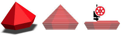
Layer height Layer height is the height of the each printed layer. The shorter the layer height, the finer the print will be. Although 3D prints with thinner layers results in a higher resolution and smoothness, it also result in a longer printing time. Hence, I recommend choosing a layer height of 0.2mm to balance the amount of filament used, printing time and resolution of the design.

Infill density and Infill pattern Infill density controls the amount of fill in the internal cavities. A higher infill gives more strength but at a cost which are longer printing time. I recommend choosing infill density typically around 10-20%. I would choose an infill density of 10% for prototyping or small model. Additionally, I would generally choose an infill density of 20% when finalizing my 3D model. However, if your 3D model is large, it may require a higher infill density up to 35%. Lastly, try not to select an infill greater than or equal to 50% as it is a waste a lot of time and material.

Infill patterns is the type of shape that takes up space inside a print, it is designed for structure works. I recommend choosing infill patterns such as grids, lines, honeycombs as well as rectilinear or concentric patterns as they work best. However, my favorite infill pattern has got to be honeycombs as a man once said "Hexagon are the bestagons".

Support Supports are used to aid printing overhangs and make the impossible happens. They are removed after the print is completed. They are mainly used to prevent overhang limits and bridging. However, support help create 3D model with those issue. There is a catch though, it adds print time as well as touch-up and finishing time to the model. Hence, the orientation of the 3D model in the slicing software is very important as it helps in the determining of supports.
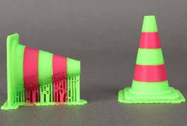
Plate adhesion The print bed is usually heated to improve adhesion and sometimes it requires help in adhering to the print bed. There are 3 types which are skirt, brim and raft. Skirts are used to outline without adhesion. This is a great way to help prime your extruder and establish a smooth flow of filament. The best part is that it saves time and materials! Brim are used to hold down the edges of your part which can help prevent warping and help with bed adhesion. Lastly, raft are used to help stabilize models with small footprints as well as to create strong foundation for the 3D models. I highly recommend using skirts as it saves a lot of time and materials in the long run!

You have now learnt what to prioritize for your 3D design model. Do note that you should balance the options mentioned above to efficiently 3D print your model. As a result, you will minimize materials used as well as the time to 3D print. With the settings completed, it is time to save your file as a gcode. This will help convert the layers into instructions for the 3D printer. Now that we are done with the preparation for 3D printing , lets move onto the next step!
3D Printing
Here comes the best of 3D printing! Before starting to 3D print, there are two important things to take note of. Firstly, ensure that the 3D printer has enough filament so that the process will not be disrupted. Secondly, ensure that there are no resins left from previous use. Once checked, it is time to start printing by transferring the gcode to the 3D printer! Onto the next step!
Post-processing
It's time for the best or worst feeling of 3D printing! Carefully remove the 3D model from the build plate by bending it and remove any support structures. If the 3D model does not function as intended, that's okay as 3D printing is all about trial and error. There is also no risk in trying again. However, if it does work, congratulations! It's time to do some finishing touches to make the 3D model perfect. You can sand, paint or assemble the 3D model if required.
Congratulations! Give yourself a pat in the back. You have now learnt the 5 essential steps to create your very own 3D printed model! It's time to move onto the juicy part of the blog!
3D Printing Assignment
It's time for the juicy part of the blog! I was "recently" given an assignment on 3D printing about a month ago. The assignment was to design and create a print-in-place artefact with at least one moving joint. This assignment seems easy right? Well actually no as the most difficult part was to print it in less than 60 minutes. Fortunately, the design did not need to be original and I was allowed to follow tutorial videos on online.
Step 1 (Nostlagia)
Now that I have understood the task clearly, it's time for idea conceptualization! I began searching for joint ideas and I came about on iris mechanism. A video on the top will show how it works. It's such a cool innovation and I wanted the idea come to life. So why did I chose this idea? Well it's because I remember watching a video on how the Mercedes-Benz Stadium roof worked back in 2020. Thinking of the iris mechanism made me realized that Mercedes-Benz Stadium which has the same working principle. Did you know iris mechanism is present in the big camera? And no it's not the iphone or andriod but on cameras from Sony!
I am not done yet, I still have to come out with the dimensions of the 3D model. Fortunately, I found a detailed tutorial on how to create on YouTube! This will help me complete step 1 and save me so much trouble or so I thought. I never realized why this would not be possible as print-in-place 3D model until later on. It's time for the next step!
Step 2 (Happiness)
Step 2 is 3D modelling and I followed the instructions given in the YouTube video above. As a result, the 3D model will eventually look like this as shown below which looks really cool. I didn't have any problems in step 2 as I was just following instructions. It felt that I was progressing really quickly and would not face any difficulty at all. However, that would change in step 3.
Step 3 (Anger)
It's time to slice our 3D model in UltiMaker Cura and this gave me a lot of problems. Remember about the maximum printing limit I mentioned earlier? It was about to be my worse enemy of all time. Having a maximum of 1 hour printing time was about to be the hardest challenge of this assignment. When I insert the file into the slicing software. The total printing time came out to 7 HOURS and 17 MINTUES and I am NOT exaggerating!!! I even chose the options mentioned earlier to be the worse to minimize my printing time.

The layer height and infill density was set to 0.2mm and 10% respectively. I also set my infill pattern to be grid and generated supports due to the bridging that was present underneath the 3D model. I knew I had to scale it down or change 3D design model.

With the 3D printing time to be about 7x the maximum limit, I knew I had to scale the design down. Since I didn't want to redo the entire tutorial video again, I did a "big" brain move which was to scale it down so that the printing time would be a maximum of 1 hour. Using the scale function under modify tab , I set the scale factor down to 0.5 which significantly decrease my printing time. Additionally, I set the layer height to 0.1mm because of the internal offset. I also set the infill density and pattern to 20% and grid. Supports were generated because of the backside as there was a overhang and skirt was used. In conclusion this will help balance the 3D printing time and strength. Let's move onto the next step!
Step 4 (Calmness)
There wasn't any preparation to be be done or problems while 3D printing. Instead, I will show you a short timelapse of my iris mechanism being printed in the video above. It's satisfying to see a short timelapse video on a model being 3D printed.
Step 5 (Disappointment)
When I first got the iris mechanism after 3D printing, I was disappointed seeing my effort gone to waste. However, after some time, I would realize why my 3D model design would not suffice. Firstly, the arm was subjected to overhang which will generate supports that are difficult to remove. Secondly, the offset was very small which caused iris mechanism to be printed as one part. But wait, couldn't I increase the offset between the parts which would solve most of the issue? Yes I could but removing the supports was the most challenging part which can damage the overall model. The most important thing was that the 3D model is best printed in parts which would defeat the purpose of the assignment. Hence, the idea of iris mechanism was scrapped.
Back to Step 1
Since my first design was a total disaster, it's time to go back to the drawing board. I was searching about different types of 3D printed-in-place design on Google on ideas again. I saw an idea about gyroscopes which sounded so cool. I remember being fascinated on how it worked. If you are curious to how gyroscopes works, there is a video down below which you will learn a lot from!
With the idea conceptualization done again, I went to search on YouTube. There was a video on YouTube which caught my attention.
Step 2 (once again)
Step 2 is 3D modelling which was also simple since all I had to do was to follow instructions once again. I also did not had any trouble doing this portion and I was able to learn about the revolve function. The 3D design will look like the one below.
Step 3 (almost there)
It's time to slice our 3D model again!! This time the time taken is much shorter than expected at ONLY 24 Minutes! I chose the following options and it's reasons.


I set the layer height to 0.2mm because of the small offset of 0.4mm between the gimbals. Having a layer height smaller than 0.4mm is required to ensure the functionality of the gyroscope keychain. Hence, 0.2mm will be sufficient to balance the amount of filament required and time taken.
I set the infill density to be 10% with a grid pattern. Since my gyroscope keychain is small, there is no reason for a higher fill. This will maximise the functionality of the gyroscope keychain while reducing print time. Thus, saving time and costs.
I set the build plate adhesion type to skirt. This helps to stabilise the flow of the filament through the nozzle to minimise any print failure, saving time and costs required to produce the design.
I orientated the gyroscope keychain to be flat as shown in figure 5 which eliminates the need for support for the gyroscope itself. Initially, I added supports for the keychain portion due to the overhang greater than 45 degrees. However, when I was printing using the new 3D printer which I will mention later on, there was no need while printing the gyroscope keychain due to the short 4mm overhang distance. Hence, selecting no support is recommended to save time and costs.
Step 4 (Panicking)

I used this 3D printer also known as Bambu lab x1c on the left and my experience was fantastic. It can print my gyroscope without any difficulty. Additionally, it can do so very fast with high quality. Compared to other printers such as the Ultimaker 2+ or Cubicon Style 3D printers. Overall I am very happy with the performance of this 3D printer. Similarly to the first design, there were no preparation or problems when using this 3D printer
Sorry if the video was not stable as it was tiring standing for at least 15 minutes straight while holding my phone nicely. The short timelapse of the Bambu lab X1C printing my gyroscope keychain is still nevertheless satisfying.
Step 5 (Moment of truth)
Retrieving my gyroscope keychain at this point was very scary as I did not know if it would work. I would be demoralized if it still does not work. Thankfully, it worked this time as shown in the video below and I did not had to do any finishing touches.
As you can see, the gyroscope keychain works as intended as it is able to move freely while the gimbal does not fall off freely. With that, I have completed my assignment!! WOOHOO!! Okay, but why do I need to do this assignment in the first place? It's to teach us the advantages of using addictive manufacturing over subtractive manufacturing. let's move onto the next part to share more about the advantages and my write up.
Gyroscope Keychain
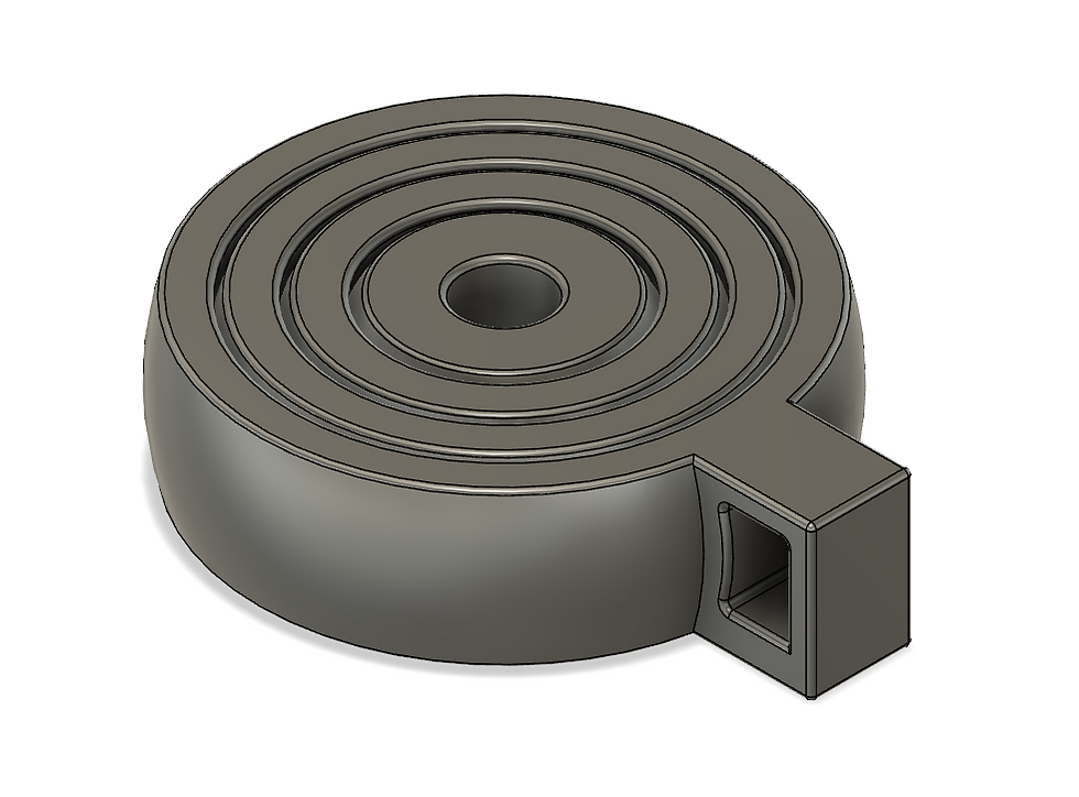
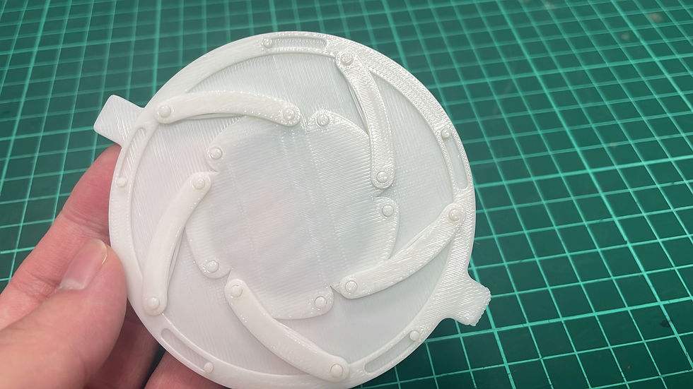
Figure 1: Print-in-place gyroscopic keychain
The gyroscopic keychain features to have 3 flawless joints that can be used after 3D printing.
Why the design cannot be easily manufactured using subtractive technologies:

Figure 2: Side view of the design.
The first reason is the complexity of the design, which makes it complicated to construct using subtractive technologies. Complicated internal features present in the design pose a challenge for these technologies. This is because of the internal accessibility for shaping the complex internal structure. For instance, Figure 2 above illustrates the interior shape of the gyroscope that features a concave gimbal, which requires advanced subtractive technologies or must be manufactured in sections and then assembled. As a result, the design significantly increases the cost and time when using traditional manufacturing.
The second reason is the requirement for precise alignment and precision in the design that makes it challenging for subtractive technologies. Accurate alignment and precision are necessary for the functionality of the gyroscope. The design in figure 2 illustrates an offset of 0.4 mm between the gimbals. The complex concentric gimbals and offset require advanced machine operations to produce the design. Additionally, maintaining accurate alignment throughout the process will be challenging for the subtractive technology. Hence, increasing the time and costs of the design.

Figure 4: properties of gyroscope keychain
The third reason is the technique that subtractive technology uses. Subtractive technology involves a process that removes a material from stock using a rotating or stationary tool until it achieves the desired shape. This method wastes a ton of material, as shown in figure 3. It requires a block with a dimension of 40mmx48mmx12mm, bringing a total volume of 23040mm^3. However, the design only requires 13524.302 mm^3, as shown in Figure 4, which wastes almost half of the original dimensions. Additionally, this method also limits the capacity to build complicated interior geometries while maintaining the design’s structural integrity. Since my design is a gyroscope, it must be firmly secured at all times to avoid movement to prevent any damages during manufacture.
In conclusion, addictive manufacturing is superior to subtractive manufacturing when constructing my gyroscope keychain. Building the model layer by layer helps ensure the gyroscope keychain is aligned and precise while ensuring its functionality. Additionally, it helps to efficiently print with minimal waste, which saves costs and time compared to subtractive manufacturing. Hence, addictive manufacturing excels at producing complicated structures.
Now that you have learnt why my design cannot be easily be manufactured, let's jump right into the next step!
Reflections
Unfortunately, there is no more steps to continue and every good journey comes to an end. This will be final blog and I will be now talk about my reflections on my chemical product design journey. Let us recall back to our first blog where I mentioned about my learning goals and have I achieved them?
First Goal: Being better at problem-solving
I will know I have achieved this goal when I am consistently spending less time solving a problem. To achieve this, I will apply the CDIO framework as it is highly effective technique for problem-solving.
Second Goal: Being better at 3D AutoCAD software
I will know I have achieved this goal when I have created a well designed chemical product with feedback from others. To achieve this, I will practice using the 3D AutoCAD software everyday and trying out different functions to understand the software better.
Have I achieve it?: Being better at problem-solving
Although I did not time myself when I encounter each problem, I have been using different techniques to help me solve my problems as mentioned from my previous blogs. It has significantly helped me solved my problems by making small baby steps. Overall, I feel that I have become better at problem-solving.
Have I achieve it?: Being better at 3D AutoCAD software
Even though my chemical design product might not be perfect, I have definitely became better at 3D AutoCAD software. From my previous blogs, I have learnt many different functions and I got to use them. Similarly, I learn many different functions such as scaling, revolve and the physical property of the 3D model.
In conclusion, I personally think that I have achieved both of my goals during my chemical product design.
The End
As we move to the end of my chemical product design journey, I have learned many different things from how plastics can both help and hurt us to the difference between addictive and subtractive manufacturing. I have also managed to refine both my soft and technical skills which are my learning goals.
I hope that you enjoy the previous blogs that I have put my heart and soul into and I had a lot of fun making these blogs. it's time to say my final goodbye!
With that, it is time to wrap my fourth blog on my chemical product design. journey. I hope you have a great time reading and see you next time. Bye bye! :)


Comments