Blog 3: Design for 3D printing
- nicholasleejh05
- Jul 12, 2024
- 15 min read
Updated: Jul 20, 2024
Hey you, miss me? It's been 7 weeks since my last blog and it's time for another one. Buckle up because I have so many things to share, but first, recap time!
In my second blog, I briefly talked about Autodesk Fusion 360 and what I have created in 2022. If you don't remember, I had to create a fidget spinner, and my final design looked like this!


After a two-year break, I have returned to using Autodesk Fusion 360. In the last lesson, I had to design a key-ring tag. Even though I may not be as skillful as before, I still found the tasks easy as pie!
Autodesk fusion 360 is such an amazing tool for designing our ideas. It allow us to create detailed accurate models. However, turning our creation into a reality is where 3D printing shines.
3D Printing (FDM)
Did you know that there are three types of 3D printing: FDM, SLA and SLS? I used to think that there were only one type of 3D printing but what's the difference and how do they work? I only had the chance to use FDM printing back in 2022, so I will be talking about it only.

Fused deposition modeling (FDM) printing or also known as fused filament fabrication (FFF) is the most common type of 3D printing utilised by consumers. It uses a process called additive manufacturing (AM) which construct models by depositing melted materials layer by layer in a pre-determined path. Although FDM printing used melted materials, it only uses materials such as PolyLatic Acid (PLA), Acrylonitrile Butadiene Styrene (ABS) and Thermoplastic PolyUrethane (TPU). I like to think that FDM printing is like using hot glue to construct the model. The process is so simple and quick that it's no surprise many people uses it!
What's so special about the process? Firstly, we need to understand what digital fabrication is! In simple terms, digital fabrication is a process where computers control machines to make different shapes and parts using digital data. The data mostly come from computer-aided design (CAD) which is then transferred to computer-aided manufacturing (CAM) software. The CAM software produces data that guides specific machines using additive and subtractive manufacturing tools.
But what's the difference between additive and subtractive manufacturing? Subtractive manufacturing is the process of removing material from stock. It uses rotating or stationary tools to strip the material away until the object takes the right shape. The vast majority of modern subtractive machine have not changed over the past few decades as they are matured technologies. Some examples would include turning, milling and profile cutting. Addictive manufacturing however, uses data from CAD software or 3D object scanners to deposit materials to create the object. Although traditional subtractive manufacturing is effective for mass production, it struggles to meet the demand of short product development lifecycles. That's where additive manufacturing (AM) comes in, offering much greater flexibility and efficiency. Additionally, AM requires lower capital to produce a product and is more economical overall.

Everything has its advantages and disadvantages, including FDM printing. When it comes to accuracy and detail, FDM is surpassed by SLA and SLS. Additionally, the biggest problem with FDM printing has is overhang which severely limits the creative possibilities of the design. Nevertheless, FDM printing is still an excellent way to create a prototype! Now we know more about 3D printing (FDM specifically) and how it works! Wow, we learned so much, I think that is enough theory for today. 🤓
Take a look at how cool this FDM 3d printing machine looks!
<-------------------
Application
Now that we have learnt more about 3D printing, it's time to unleash our creativity! There are so many cool ideas that have been created using 3D printing. There are many websites such as https://www.thingiverse.com/ that allows you download other people's design and the best part is it's FREE! Since I loved cars from young, there is a video that have peaked my interest. The video shows a reverse engineered Subaru WRX EJ20 4 cylinder boxer engine with a 5 speed manual transmission from a Toyota 22RE engine. It's amazing to see the capabilities of 3D printing today and who knows what other amazing feats it can achieve in the future!
Another video that have caught my attention will be this fully powered jet engine that is capable of running at 1865 RPM. It is impressive how this 3D printed jet engine can withstand at such RPM with half its frame. As you have noticed, both videos shown are about engines and I love them a lot!

It is amazing what crazy potential 3D printing have on the engineering industry. This got me thinking if 3D printing will be used to produce engines in 10-15 years time? In the early stage, 3D printing specifically addictive manufacturing has been only limited to prototyping. It allows engineers to physically evaluate the design. They can also print numerous design iterations to identify and remove errors by performing functional testing before committing to a full production. However, addictive manufacturing is now good for end use parts as well! Addictive manufacturing technology have improved so much over the years that it can produce parts that are as good or even better than parts produced by traditionally technologies. Addictive manufacturing brings so much advantages such as making products lighter, saving costs and can be printed in hours not days! Hence, I think this answers my question and I personally think it is possible that 3D printing will be mainly used to produce engines in the future! With that, it's time to move on to the next part of the blog!
3D modelling

WOOHOO, it's time for BEST part! 🥳 I was recently given an assignment on 3D modelling and printing which bring me back to when I did my fidget spinner assignment. This assignment was different as I had to design a casing for the probe to prevent the electrical connection from direct contact with water when the plant is watered. This assignment have made me improved my skills in Autodesk Fusion 360 and I will share more about with you too!

I really enjoyed this assignment because of its difficulty. I was originally going to create a small box with holes small enough for the wires to fit through only. However, my lecturer told me that I had to step up as I had prior experience with Autodesk Fusion 360. This got me wondering "how does one design a casing that is small but is able to stand out from other design?" I found that question the biggest challenge in this assignment. Look how small the moisture sensor is compared to my fingers!
Designing


This design was the "first" that I have created for the model. Surprisingly, the idea did not originate from me but was actually suggested by my lecturer. He helped me to visualise and think outside of the box. Although I think it's a very good idea, I thought that there will be some problems such as inserting my moisture sensor and mainly 3D printing.
You might be wondering why is 3D printing a challenge when designing a model in this scenario? It is because it can cause overhang which will result in a lower quality or failed prints. Hence, I decided to scrap the idea.
At this point, it feels like I've gone from the final step back to the first, even though I have not begun. But that's okay as it is normal when it comes to designing. It is all about trial and error! This reminds me when I was doing my design and technology (DnT) subject where I had to keep changing my design several times and it was NOT fun at all. If you recall from the last blog, I switched my strategy to the DCHE SD model and found success and I will continue using it. Additionally, I decided to incorporate the CDIO framework as well.


So how did I manage to complete this assignment? Firstly, I reread the provided slides to find any helpful clues. Secondly, I tried to recall on what my lecturer mentioned, including the suggestion that our design could come from the internet. With my first clue, I searched up on the internet to find existing casing for the plant moisture sensor. Some ideas were helpful and others were rather interesting. One an example that was rather interesting is shown on the right which looks like the person 3D printed on the plant moisture sensor itself.

One helpful example was this design shown on the left which helped my final design. However, I did not use this design for 2 reasons. Firstly, the water can still enter from the sides and the casing does not have a snap fit to hold it in place. Now that I have researched more about different types of design, it's time to design one myself.

Remember the question I have mentioned earlier? "how does one design a casing that is small but is able to stand out from other design?" From my DnT experience, I adopted a technique that involves integrating parts from different objects into a single design. The first part that I integrated was a dovetail box with sliding lid and a snap fit joint. The plant moisture would be ergonomic and easily used without water sipping through the cover. The casing would look like the picture below
The design shown up incorporates the considerations of both ergonomics and functionality. The sliding dovetail lid at the top is easily removeable to insert the plant moisture sensor and prevents water from sipping through because of its trapezium shape. I also incorporated the tube liked section from draft 1 and improved it to have a circular snap fit. This will allow users to insert the wire through the hole easily. I have also made the hole circular to ensure that overhang is unlikely to occur during 3D printing.

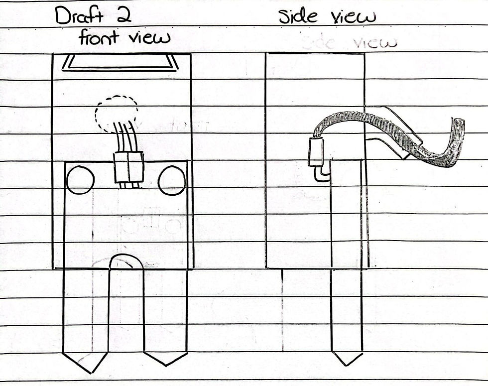
While this looks good on theory, there is one problem with this. Since the moisture sensor is small, the cover will also have to be small. It will not make sense if the cover is 10 times the size of the moisture sensor. Additionally, since the snap fit joint have to be flexible, a thin one would more likely to break. Hence, I did not use snap fit joint in my final design which is shown on the right.
Instead of a circular tube for the wire to pass through, I designed such that the wire will travel below the cover. You may be wondering that wouldn't that reduce the ergonomic of the casing? 🤔 Yes, it will since it is harder to insert the wire. However, the user would only remove and insert the plant moisture sensor for maintenance or other infrequent reasons. Additionally, the casing will still be able to serve its main purpose which is to keep the prevent the electrical connection from direct contact with water when the plant is watered.
Now that we have completed our design for our casing, it's time to go back to my main question which is "how does one design a casing that is small but is able to stand out from other design?" Now, have I designed something that stands out from the rest? I have no idea but I have definitely designed a casing small enough👍. With that, we have completed our design and it's time for our next step. Yippee! 🥳
Measurement

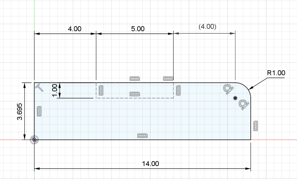
It's time for measuring! This section is the most important part in order for our casing to work. Hence, it is very important to measure properly. The dimensions can be found on the right. Before we create our design on Autodesk Fusion 360, what are some important measurements do we need to take note of? 🤔
Some common measurements will include the length, width and thickness of the plant moisture sensor. But why did I only measure a fraction of the length? It's because that is the area where it will be covered. Hence, there is no need to measure the probe as it will be exposed.
I have also written the design considerations of the casing which will be shown below:
1. The model has an inner dimension of 22x10x42mm. This will allow the moisture sensor module to fit neatly inside with enough clearance.
2. The black board and pin connector have a length of 13.5mm and 14mm, respectively. Hence, the inner height of the cover is 42mm to ensure that the wire can be bent 180 degrees.
3. To fit the moisture sensor module, there is a sliding dovetail lid at the top of the model, which has a clearance of 0.25mm. This is enough to slide the lid and prevent water from leaking into the model due to its small clearance and trapezium shape.
4. The sliding dovetail lid is slanted at 55 degrees inward to prevent overhang for 3D printing.
5. The model has two large rectangular holes at the bottom that have a dimension of 8x1.8mm. The length in between is 6mm, which is wide enough for the probe to fit through without the electrical connection being in direct contact with water when the plant is watered.
6. The model has one large rectangle hole that has a dimension of 6x4mm, which is enough for two cables to fit through. The outlet for the wire comes out at the bottom to prevent any leaks if the outlet is placed at the side or the top.
Before we can move on to create our casing in Autodesk Fusion 360, we first have to know the dimensions of the model!
Box Top/Bottom view

Box Front View

Box Side view

Lid top view

Lid Front view

Lid Left Side View
We have completed our measurements and it's time to design our casing in Autodesk Fusion 360!
Creating using Autodesk Fusion 360.
It's time to create our casing in Autodesk Fusion 360 and I have learn so many things about it! I will share you how I created my casing step by step and sit back and relax because this is going to be a long tutorial. It is going to get extremely detailed...
Box: Step 1-47
Lid: Step 48-53
Step 1:
Click on "Assemble" then select "New component" from the dropdown menu

Rename "component 1" to "Box" under the name section and click "Ok"

Step 2:
Click on "Create" then select "Box" from the dropdown menu


Step 3:
Click on the horizontal plane.

your screen should look like this when done correctly

Step 4:
Click on the origin to start the box size 30mm x 18mm. Use the “TAB” button on the keyboard to toggle between Breadth and Length. Once done, press ENTER once.

Step 5:
An input dialogue box will appear, input 50 mm for the height and click "Ok"

Step 6:
Left Click on the top part of model and ensure that it is blue as shown

Step 7:
Click on "Modify" and then select "Shell" under the dropdown menu

Step 8:
An input dialogue box will appear, input 4 mm for the inside thickness and click "Ok". Ensure that the direction is "inside".

Step 9:
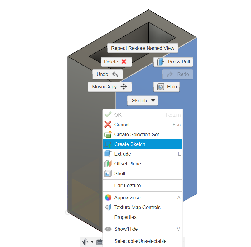
Left click on the right face and ensure that it is blue as shown in the picture below. Right click and a dropdown menu will appear. Select "create sketch".
Step 10:
Click on the orbit function below (highlighted blue) and rotate the model to this position.

Step 11:
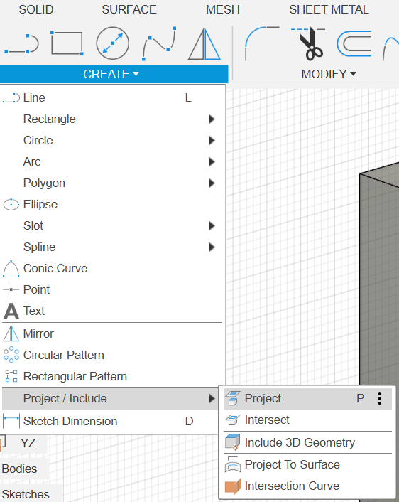
Click on "Create" and hover your cursor on "project/include" followed by selecting "Project"
Step 12:
Click on the line highlighted in blue and click "Ok" .A purple circle will be shown when done correctly.

Step 13:
At the top right hand corner, Click on the "right" plane as shown


When done correctly it should look like this ---->
Step 14:
Click line button (highlighted blue)

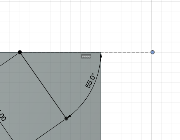
Step 15:
Click on the purple circle at the right hand side. Ensure that it is 55 degrees outwards and the length at 4mm. Use the “TAB” button on the keyboard to toggle between the angle and length. Once done, press ENTER once.

Step 16:
Click on "select" button (highlight blue)

Step 17:
Click on the white circle and drag it to any length outwards

Step 18:
Hold down SHIFT button on the keyboard and click on the two circles as shown. It will turn blue when done correctly.

Step 19:
Click on the coincident button highlighted in grey

Step 20:
Click on the line button (highlighted blue)
Step 21:
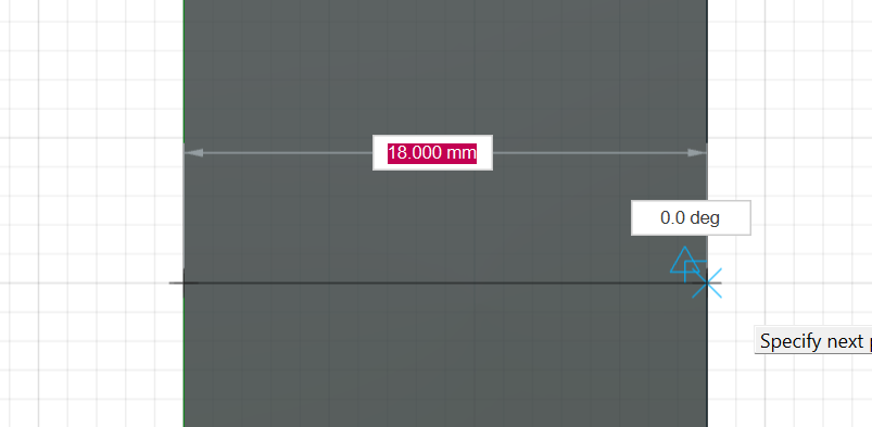
Hover you cursor on the line till it is at the middle point. A triangle will be shown when it is at middle point.

Left click and drag when the length is 5mm and is at 90 degrees. Use the “TAB” button on the keyboard to toggle between the angle and length. Once done, press ENTER once.

Step 22:
Hold down SHIFT button on the keyboard and click on the two circles as shown and double click on the "Horizontaol/Vertical button" (highlighted blue). It will turn blue when done correctly.

Step 23:

Step 24:
Click on the middle line and select "construction" (highlighted blue) under the sketch palette.

Step 25:
Click on the line button (highlighted blue)
Step 26:
Connect the two dots as shown below and press ENTER

Step 27:
Click on the "mirror" button that is highlighted blue.

Step 28:
For objects, click on the lines that are highlighted in blue.

Step 29:
For the mirror line, click on the dotted line that is highlighted in blue and click "Ok".

Step 30:
Click on "Solid" followed by the extrude button that is highlighted in blue.

Step 31:
Click on the trapezoid that is highlighted in blue.

Step 32:
Click on the home button at the top right hand corner.

It should look like this when done correctly.

Step 33:
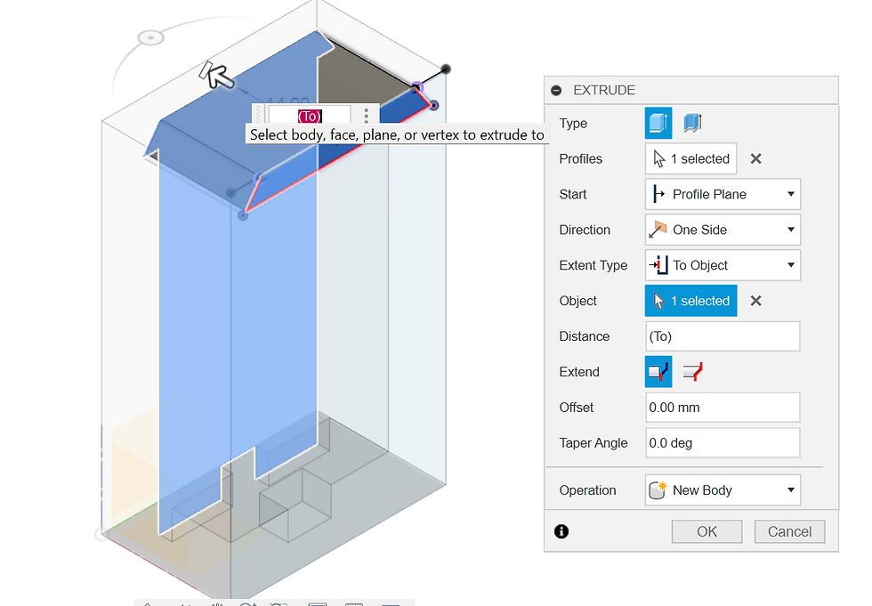
The extent type should be "to object" as shown below.

Step 34:
For the object, select the back of the face (highlighted purple) or the face with the arrow pointing backwards as shown and click "Ok".

Step 35:
Rotate the model at the top right hand corner till it is at the bottom as shown below

Step 36:
Left click on the face and it should appear blue. Right click and select "Create Sketch" under the dropdown menu.

Step 37:
Click on the line button (highlighted blue)
Step 38:
Hover you cursor on the line till it is at the middle point of the side with the longest length. A triangle will be shown when it is at middle point.Draw a line in the middle of the rectangle.
Click on the middle dotted line and select "construction" (highlighted blue) under the sketch palette.

Step 39:
Click on the 2-point rectangle button (highlighted blue)

Construct a square that is 4mmx4mm as shown below. Ensure that it is a construction line.

Step 40:
Deselect the construction line under the sketch palette and ensure that it is not highlighted.

Click on the 2-point rectangle button (highlighted blue)
Construct a rectangle that is 1.8mm x 8.5mm as shown below and press ENTER once.

Step 45:
Click on the "mirror" button that is highlighted blue.
Select the 4 lines that are highlighted in blue for the objects

Select the line that is highlighted in blue for the mirror line and click "Ok".

Step 46:
Click on the 2-point rectangle button (highlighted blue)
Construct a rectangle that is 12mm x 4mm as shown below and ensure that it is a construction line under the sketch palette and press ENTER once.

Click on the 2-point rectangle button again (highlighted blue)
Deselect the construction line under the sketch palette and ensure that it is not highlighted.
Construct a rectangle that is 12mm x 4mm as shown below press ENTER once.

Step 47:
Click on "Solid" followed by the extrude button that is highlighted in blue.
Holding the SHIFT button on the keyboard, left click the 3 rectangles that we have just made (highlighted in blue)

Ensure that the distance is set to "-4mm" and the operation is set to "Cut". Once done, click "Ok".

A hole will be created at the bottom when done correctly.

Step 48:
Click on "Assemble" then select "New component" from the dropdown menu
Rename "component 2" to "lid" under the name section and deselect the parent by pressing on the cross.

Select the word "Unsaved" at the top left hand corner and click "Ok".

Step 49:
Left click on the plant that is highlighted blue and right click. Select "create sketch" from the dropdown menu.

Press "P" and select the 4 lines that make up the trapeziod and click "Ok".

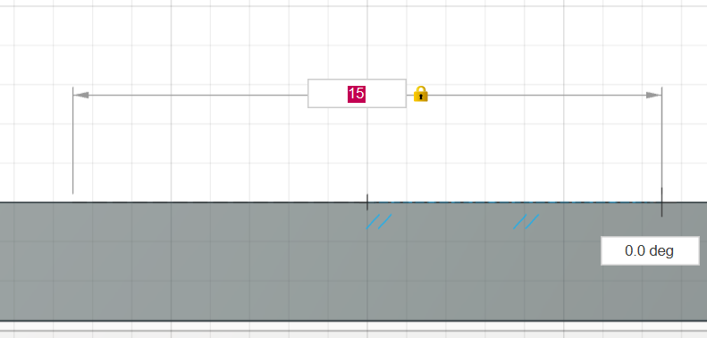
Select the offset button that is highlighted in blue.

Uncheck the chain selection in the menu and select the blue lines accordingly. Ensure that the red line is facing outwards with a offset position of "0.25mm". Once done, click "Ok".

Click on the line button (highlighted blue)
Using the line tool, draw a straight line on the purple line as shown and press ENTER once.

Step 50:
Click on "Solid" followed by the extrude button that is highlighted in blue.
Click on the trapezoid that is highlighted in blue.

Click on the home button at the top right hand corner.
Select the extent type to "To object", For the object, select the plane (highlighted in blue) or the side opposite of the trapezoid. Once done, click "Ok"
Step 51:
Left click the plane highlighted in blue and right click. Select "Create Sketch" from the dropdown menu.

Click on "create" and then select "ellipse" under the dropdown menu.

From the midpoint, set the length to 15mm and drag to set the height at 2mm. Once done, click ENTER once.

Step 52:
Click on "Solid" followed by the extrude button that is highlighted in blue.
Click on the home button at the top right hand corner.
Click on the blue highlighted ovel and set the settings as shown in the extrude menu. Ensure that the offset is set to a negative value and the start is set to offset. Once done, click on "Ok".

Step 53:
Click on the fillet button highlighted in blue

While holding SHIFT button on keyboard, select the following 10 lines that are highlighted in blue.
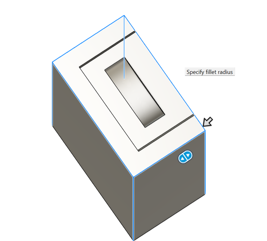
Set the fillet to 1mm and press "Ok".

Wow after 53 steps, we are finally done designing our casing! give yourself a pat on the back. 🥳If you want to see the casing without creating, I have l embed my Fusion design file below. The casing looks so good in the matt black paint.
Learning more about Autodesk Fusion 360
You may wondering whether I did everything by myself? The answer is no as I used some helped from a YouTube video that is down below. I learned about the different functions such as shell, project/include, animate and the new component.. The coolest thing I have learned was about the "change parameters" function where I can change one part without redoing the whole thing! I did not expect myself to be learning so many things just from 1 video. Now that I think about it, I realise I've barely scratched the surface of Autodesk Fusion 360 functions. There are so many other functions that I have yet to try, like the mesh and utility sections. Autodesk Fusion 360 is really impressive software and I think the creators thought of everything.
With that, it is time to wrap my third blog on chemical product design. I had an amazing time learning about many different things from 3D printing to Autodesk Fusion 360 functions. I hope you have a great time reading and not to worry there are more coming soon. But for now, see you next time. Bye bye!
References
Ideal3D. (n.d.). Ultimaker 2 Extended. [online] Available at: https://ideal3d.be/boutique/3dprinters/ultimaker-2-extended-2/ [Accessed 11 Jul. 2024].
ResearchGate. (n.d.) Research Gate [Online] Available at: https://www.researchgate.net/figure/Overhang-tests-showing-different-printabilities-and-finish-qualities-at-seven-different_fig5_331575569. [Accessed 11 Jul. 2024].
ResearchGate. (n.d.) Research Gate [Online] Available at: https://www.researchgate.net/figure/CDIO-framework-of-planning-a-training-program_fig2_343663180 [Accessed 11 Jul. 2024].
Pinterest. (n.d.). Pin on Mechanical Design. [online] Available at: https://www.pinterest.com/pin/807903620640109379/ [Accessed 11 Jul. 2024].
Cscan.co. (2024). camscanner-share. [online] Available at: https://cscan.co/3eZKs02hg6S [Accessed 11 Jul. 2024].
Cscan.co. (2024). camscanner-share. [online] Available at: https://cscan.co/3eZE4018zdw [Accessed 11 Jul. 2024].
www.youtube.com. (n.d.). Sliding Dovetail Lid for 3D Printed Box | Fusion 360 Tutorial. [online] Available at: https://www.youtube.com/watch?v=HMtLqm5TkGE. [Accessed 11 Jul. 2024].
DVIDS. (n.d.). McConnell Instructor 3D Prints Jet Engine Models. [online] Available at: https://www.dvidshub.net/news/440515/mcconnell-instructor-3d-prints-jet-engine-models [Accessed 20 Jul. 2024].


Comments